上帝视角 | 多核系统的负载均衡
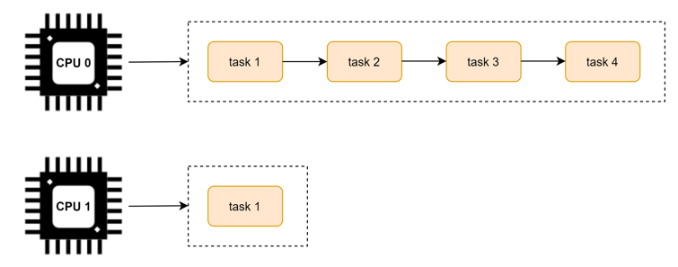
前面的调度学习都是默认在单个 CPU 上的调度策略。我们知道为了 CPU 之间减少“干扰”,每个 CPU 上都有一个任务队列。运行的过程种可能会出现有的 CPU 很忙,有的 CPU 很闲,如下图所示:
因为负载均衡是在多个核上的均衡,所以在讲解负载均衡之前,我们先看下多核的架构。
将 task 从负载较重的 CPU 上转移到负载相对较轻的 CPU 上执行,这个过程就是负载均衡的过程。
多核架构
这里以 Arm64 的 NUMA(Non Uniform Memory Access) 架构为例,看下多核架构的组成。
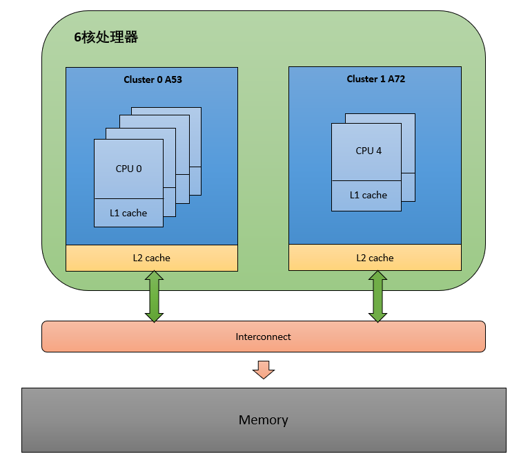
我们知道一个多核心的 SOC 片上系统,内部结构是很复杂的。内核采用 CPU 拓扑结构来描述一个 SOC 的架构,使用调度域和调度组来描述 CPU 之间的层次关系。
CPU 拓扑
每一个 CPU 都会维护这么一个结构体实例,用来描述 CPU 拓扑。
struct cpu_topology {
 int thread_id;
 int core_id;
 int cluster_id;
 cpumask_t thread_sibling;
 cpumask_t core_sibling;
};- thread_id: 从 mpidr_el1 寄存器中获取
- core_id:从 mpidr_el1 寄存器中获取
- cluster_id:从mpidr_el1寄存器中获取
- thread_sibling:当前 CPU 的兄弟 thread。
- core_sibling:当前 CPU 的兄弟Core,即在同一个 Cluster 中的 CPU。
可以通过 /sys/devices/system/cpu/cpuX/topology 查看 cpu topology 的信息。
cpu_topology 结构体是通过函数 parse_dt_topology() 解析 DTS 中的信息建立的:
kernel_init() -> kernel_init_freeable() -> smp_prepare_cpus() -> init_cpu_topology() -> parse_dt_topology()
static int __init parse_dt_topology(void)
{
 struct device_node *cn, *map;
 int ret = 0;
 int cpu;

 cn = of_find_node_by_path("/cpus");          ------(1)
 if (!cn) {
  pr_err("No CPU information found in DT\n");
  return 0;
 }

 /*
  * When topology is provided cpu-map is essentially a root
  * cluster with restricted subnodes.
  */
 map = of_get_child_by_name(cn, "cpu-map");   ------(2)
 if (!map)
  goto out;

 ret = parse_cluster(map, 0);                 ------(3)
 if (ret != 0)
  goto out_map;

 topology_normalize_cpu_scale();

 /*
  * Check that all cores are in the topology; the SMP code will
  * only mark cores described in the DT as possible.
  */
 for_each_possible_cpu(cpu)
  if (cpu_topology[cpu].cluster_id == -1)
   ret = -EINVAL;

out_map:
 of_node_put(map);
out:
 of_node_put(cn);
 return ret;
}- 找到 dts 中 cpu topology 的根节点 "/cpus"
- 找到 "cpu-map" 节点
- 解析 "cpu-map" 中的 cluster
以 i.mx8qm 为例,topology 为:”4A53 + 2A72”,dts中定义如下:
# imx8qm.dtsi

cpus: cpus {
        #address-cells = <2>;
        #size-cells = <0>;

        A53_0: cpu@0 {
                device_type = "cpu";
                compatible = "arm,cortex-a53", "arm,armv8";
                reg = <0x0 0x0>;
                clocks = <&clk IMX_SC_R_A53 IMX_SC_PM_CLK_CPU>;
                enable-method = "psci";
                next-level-cache = <&A53_L2>;
                operating-points-v2 = <&a53_opp_table>;
                #cooling-cells = <2>;
        };

        A53_1: cpu@1 {
                device_type = "cpu";
                compatible = "arm,cortex-a53", "arm,armv8";
                reg = <0x0 0x1>;
                clocks = <&clk IMX_SC_R_A53 IMX_SC_PM_CLK_CPU>;
                enable-method = "psci";
                next-level-cache = <&A53_L2>;
                operating-points-v2 = <&a53_opp_table>;
                #cooling-cells = <2>;
        };

        A53_2: cpu@2 {
                device_type = "cpu";
                compatible = "arm,cortex-a53", "arm,armv8";
                reg = <0x0 0x2>;
                clocks = <&clk IMX_SC_R_A53 IMX_SC_PM_CLK_CPU>;
                enable-method = "psci";
                next-level-cache = <&A53_L2>;
                operating-points-v2 = <&a53_opp_table>;
                #cooling-cells = <2>;
        };

        A53_3: cpu@3 {
                device_type = "cpu";
                compatible = "arm,cortex-a53", "arm,armv8";
                reg = <0x0 0x3>;
                clocks = <&clk IMX_SC_R_A53 IMX_SC_PM_CLK_CPU>;
                enable-method = "psci";
                next-level-cache = <&A53_L2>;
                operating-points-v2 = <&a53_opp_table>;
                #cooling-cells = <2>;
        };

        A72_0: cpu@100 {
                device_type = "cpu";
                compatible = "arm,cortex-a72", "arm,armv8";
                reg = <0x0 0x100>;
                clocks = <&clk IMX_SC_R_A72 IMX_SC_PM_CLK_CPU>;
                enable-method = "psci";
                next-level-cache = <&A72_L2>;
                operating-points-v2 = <&a72_opp_table>;
                #cooling-cells = <2>;
        };

        A72_1: cpu@101 {
                device_type = "cpu";
                compatible = "arm,cortex-a72", "arm,armv8";
                reg = <0x0 0x101>;
                clocks = <&clk IMX_SC_R_A72 IMX_SC_PM_CLK_CPU>;
                enable-method = "psci";
                next-level-cache = <&A72_L2>;
                operating-points-v2 = <&a72_opp_table>;
                #cooling-cells = <2>;
        };

        A53_L2: l2-cache0 {
                compatible = "cache";
        };

        A72_L2: l2-cache1 {
                compatible = "cache";
        };

        cpu-map {
                cluster0 {
                        core0 {
                                cpu = <&A53_0>;
                        };
                        core1 {
                                cpu = <&A53_1>;
                        };
                        core2 {
                                cpu = <&A53_2>;
                        };
                        core3 {
                                cpu = <&A53_3>;
                        };
                };

                cluster1 {
                        core0 {
                                cpu = <&A72_0>;
                        };
                        core1 {
                                cpu = <&A72_1>;
                        };
                };
        };
};
经过 parse_dt_topology(),update_siblings_masks() 解析后得到 cpu_topology 的值为:
CPU0: cluster_id = 0, core_id = 0
CPU1: cluster_id = 0, core_id = 1
CPU2: cluster_id = 0, core_id = 2
CPU3: cluster_id = 0, core_id = 3
CPU4: cluster_id = 1, core_id = 0
CPU5: cluster_id = 1, core_id = 1
调度域和调度组
在 Linux 内核中,调度域使用 sched_domain 结构表示,调度组使用 sched_group 结构表示。
调度域 sched_domain
struct sched_domain {
    struct sched_domain *parent;
    struct sched_domain *child;
    struct sched_group  *groups;
    unsigned long min_interval;
    unsigned long max_interval;
    ...
};- parent:由于调度域是分层的,上层调度域是下层的调度域的父亲,所以这个字段指向的是当前调度域的上层调度域。
- child:如上所述,这个字段用来指向当前调度域的下层调度域。
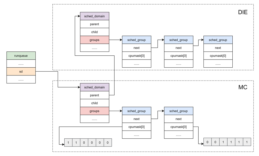
- groups:每个调度域都拥有一批调度组,所以这个字段指向的是属于当前调度域的调度组列表。
- min_interval/max_interval:做均衡也是需要开销的,不能时刻去检查调度域的均衡状态,这两个参数定义了检查该 sched domain 均衡状态的时间间隔的范围
sched_domain 是分成两个 level,base domain 称为 MC domain(multi core domain),顶层 domain 称为 DIE domain。
调度组 sched_group
struct sched_group {
    struct sched_group *next;
    unsigned int group_weight;
    ...
    struct sched_group_capacity *sgc;
    unsigned long cpumask[0];
};- next:指向属于同一个调度域的下一个调度组。
- group_weight:该调度组中有多少个cpu。
- sgc:该调度组的算力信息。
- cpumask:用于标记属于当前调度组的 CPU 列表(每个位表示一个 CPU)。
为了减少锁的竞争,每一个 CPU 都有自己的 MC domain、DIE domain 以及 sched_group,并且形成了 sched_domain 之间的层级结构,sched_group 的环形链表结构。CPU 对应的调度域和调度组可通过在设备模型文件 /proc/sys/kernel/sched_domain 里查看。
具体的 sched_domain 的初始化代码分析如下:
kernel_init() -> kernel_init_freeable() -> sched_init_smp() -> init_sched_domains(cpu_active_mask) -> build_sched_domains(doms_cur[0], NULL)
static int
build_sched_domains(const struct cpumask *cpu_map, struct sched_domain_attr *attr)
{
 enum s_alloc alloc_state;
 struct sched_domain *sd;
 struct s_data d;
 int i, ret = -ENOMEM;

 alloc_state = __visit_domain_allocation_hell(&d, cpu_map);    ------(1)
 if (alloc_state != sa_rootdomain)
  goto error;

 /* Set up domains for CPUs specified by the cpu_map: */
 for_each_cpu(i, cpu_map) {
  struct sched_domain_topology_level *tl;

  sd = NULL;
  for_each_sd_topology(tl) {
   sd = build_sched_domain(tl, cpu_map, attr, sd, i);        ------(2)
   if (tl == sched_domain_topology)
    *per_cpu_ptr(d.sd, i) = sd;
   if (tl->flags & SDTL_OVERLAP)
    sd->flags |= SD_OVERLAP;
  }
 }

 /* Build the groups for the domains */
 for_each_cpu(i, cpu_map) {
  for (sd = *per_cpu_ptr(d.sd, i); sd; sd = sd->parent) {
   sd->span_weight = cpumask_weight(sched_domain_span(sd));
   if (sd->flags & SD_OVERLAP) {
    if (build_overlap_sched_groups(sd, i))
     goto error;
   } else {
    if (build_sched_groups(sd, i))                          ------(3)
     goto error;
   }
  }
 }
  ......
 /* Attach the domains */
 rcu_read_lock();
 for_each_cpu(i, cpu_map) {
  int max_cpu = READ_ONCE(d.rd->max_cap_orig_cpu);
  int min_cpu = READ_ONCE(d.rd->min_cap_orig_cpu);

  sd = *per_cpu_ptr(d.sd, i);

  if ((max_cpu < 0) || (cpu_rq(i)->cpu_capacity_orig >
      cpu_rq(max_cpu)->cpu_capacity_orig))
   WRITE_ONCE(d.rd->max_cap_orig_cpu, i);

  if ((min_cpu < 0) || (cpu_rq(i)->cpu_capacity_orig <
      cpu_rq(min_cpu)->cpu_capacity_orig))
   WRITE_ONCE(d.rd->min_cap_orig_cpu, i);

  cpu_attach_domain(sd, d.rd, i);                            ------(4)
 }
 rcu_read_unlock();

 if (!cpumask_empty(cpu_map))
  update_asym_cpucapacity(cpumask_first(cpu_map));

 ret = 0;
error:
 __free_domain_allocs(&d, alloc_state, cpu_map);             ------(5)
 return ret;
}- 在每个 tl 层次,给每个 CPU 分配 sd、sg、sgc 空间
- 遍历 cpu_map 里所有 CPU,创建与物理拓扑结构对应的多级调度域
- 遍历 cpu_map 里所有 CPU, 创建调度组
- 将每个 CPU 的 rq 与 rd(root_domain) 进行绑定
- free 掉分配失败或者分配成功多余的内存
所以,可运行进程队列与调度域和调度组的关系如下图所示:
总结
这里用一张图来总结下 CPU 拓扑,调度域初始化的过程,如下所示:
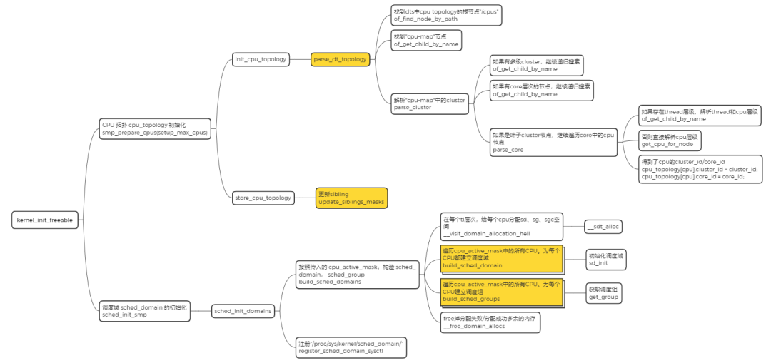

到目前为止,我们已经将内核的调度域构建起来了,CFS 可以利用 sched_domain 来完成多核间的负载均衡了。
何时做负载均衡?
CFS 任务的负载均衡器有两种:
- 一种是针对 busy CPU 的 periodic balancer,用于进程在 busy CPU 上的均衡
- 一种是针对 idle CPU 的 idle balancer,用于把 busy CPU 上的进程均衡到 idle CPU 上来。
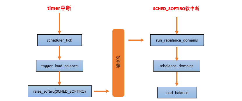
1 . periodic balancer:周期性负载均衡是在时钟中断 scheduler_tick 中,找到该 domain 中最繁忙的 sched group 和 CPU runqueue,将其上的任务 pull 到本 CPU,以便让系统的负载处于均衡的状态。
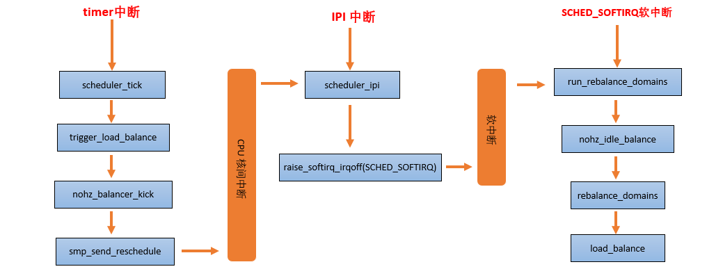
2 . nohz idle balancer:当其他的 CPU 已经进入 idle,本 CPU 任务太重,需要通过 IPI 将其他 idle 的 CPU 唤醒来进行负载均衡。
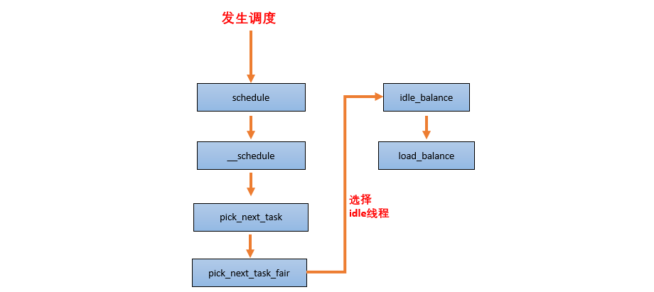
3 . new idle balancer:本 CPU 上没有任务执行,马上要进入 idle 状态的时候,看看其他 CPU 是否需要帮忙,来从 busy cpu 上 pull 任务,让整个系统的负载处于均衡状态。
负载均衡的基本过程
当一个 CPU 上进行负载均衡的时候,总是从 base domain 开始,检查其所属 sched group 之间的负载均衡情况,如果有不均衡情况,那么会在该 CPU 所属 Cluster 之间进行迁移,以便维护 Cluster 内各个CPU 的任务负载均衡。
load_balance 是处理负载均衡的核心函数,它的处理单元是一个调度域,其中会包含对调度组的处理。
static int load_balance(int this_cpu, struct rq *this_rq,
                        struct sched_domain *sd, enum cpu_idle_type idle,
                        int *continue_balancing)
{
        ......
redo:
        if (!should_we_balance(&env)) {
                *continue_balancing = 0;
                goto out_balanced;
        }

        group = find_busiest_group(&env);           ------(1)
        if (!group) {
                schedstat_inc(sd->lb_nobusyg[idle]);
                goto out_balanced;
        }

        busiest = find_busiest_queue(&env, group);  ------(2)
        if (!busiest) {
                schedstat_inc(sd->lb_nobusyq[idle]);
                goto out_balanced;
        }

        BUG_ON(busiest == env.dst_rq);

        schedstat_add(sd->lb_imbalance[idle], env.imbalance);

        env.src_cpu = busiest->cpu;
        env.src_rq = busiest;

        ld_moved = 0;
        if (busiest->nr_running > 1) {
                env.flags |= LBF_ALL_PINNED;
                env.loop_max  = min(sysctl_sched_nr_migrate, busiest->nr_running);

more_balance:
                rq_lock_irqsave(busiest, &rf);
                update_rq_clock(busiest);

                cur_ld_moved = detach_tasks(&env);  ------(3)

                rq_unlock(busiest, &rf);

                if (cur_ld_moved) {
                        attach_tasks(&env);         ------(4)
                        ld_moved += cur_ld_moved;
                }

                local_irq_restore(rf.flags);

                if (env.flags & LBF_NEED_BREAK) {
                        env.flags &= ~LBF_NEED_BREAK;
                        goto more_balance;
                }
                ......
        }
        ......
out:
        return ld_moved;
}- 找到该 domain 中最繁忙的 sched group
- 在这个最繁忙的 group 中挑选最繁忙的 CPU runqueue, 作为 src
- 从这个队列中选择任务来迁移,然后把被选中的任务从其所在的 runqueue 中移除
- 从最繁忙的 CPU runqueue 中 pull 一些任务到当前可运行队列 dst
