Device Tree语法(上)
对于DeviceTree的来历和用处大部分人都已经非常了解了,DeviceTree发源于PowerPC架构,为了消除代码中冗余的各种device注册代码而产生的,现在已经成为了linux的通用机制。
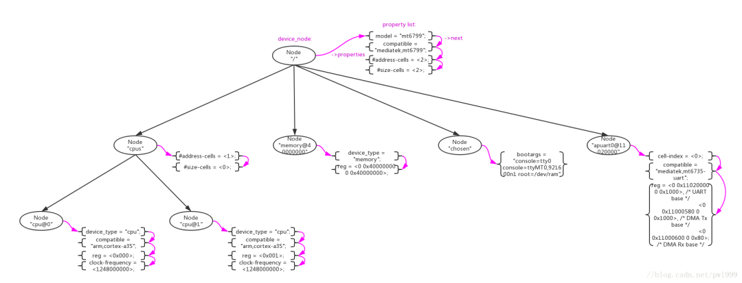
DeviceTree的结构非常简单,由两种元素组成:Node(节点)、Property(属性)。下图是一个真实的简单的DeviceTree树形结构图。
- Node节点。在DTS中使用一对花括号"node-name{}"来定义;
- Property属性。在Node中使用"property-name=value"字符串来定义;
/ {
 model = "mt6799";
 compatible = "mediatek,mt6799";
 interrupt-parent = <&gic>;
 #address-cells = <2>;
 #size-cells = <2>;

 /* chosen */
 chosen {
  bootargs = "console=tty0 console=ttyMT0,921600n1 root=/dev/ram";
 };
}
上述例子中定义了一个根节点"/"和一个子节点“chosen”,其他的字符串“model = “mt6799”;”、“compatible = “mediatek,mt6799”;”都是property。
Node、Property的名字和值都是可以自定义的,没有太大限制。但是DeviceTree的标准还是预定义了一些标准的Node和Property,在标准Node和Property之间还定义了一些约束规则。关于这些描述在 The DeviceTree Specification官方spec中有详细描述。这里为了方便大家,还是重复做一些搬运。
标准Property
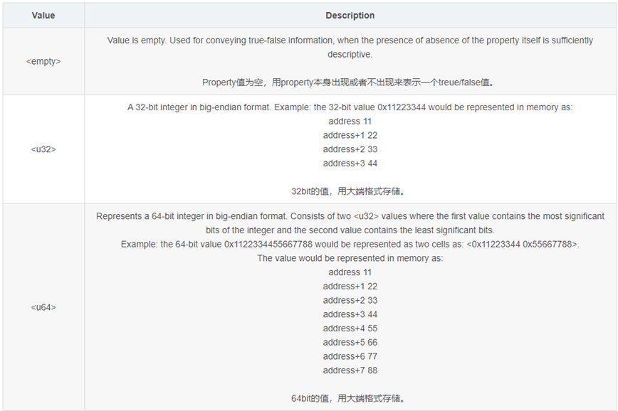
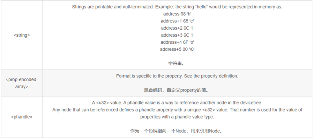
Property的格式为"property-name=value",其中value的取值类型如下:
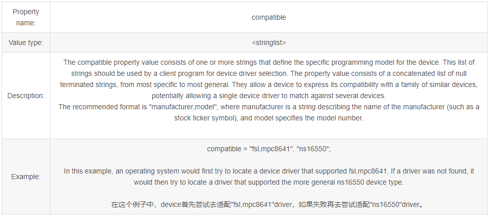
compatible
“compatible"属性通常用来device和driver的适配,推荐的格式为"manufacturer,model”。
model
"model"属性只是简单的表示型号,root节点用其来传递值给machine_desc_str。
phandle
- "phandle"属性通用一个唯一的id来标识一个Node,在property可以使用这个id来引用Node。
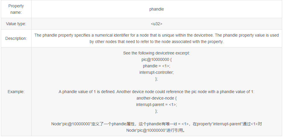
- 定义一个“label:”来引用Node,在编译是系统会自动为node生成一个phandle属性。“cpu0"是一个label,用来引用node"cpu@0”:
  cpu0: cpu@0 {
   device_type = "cpu";
   compatible = "arm,cortex-a35";
   reg = <0x000>;
   enable-method = "psci";
   cpu-idle-states = <&LEGACY_MCDI &LEGACY_SODI &LEGACY_SODI3 &LEGACY_DPIDLE>,
       <&LEGACY_SUSPEND &MCDI &SODI &SODI3 &DPIDLE &SUSPEND>;
   cpu-release-addr = <0x0 0x40000200>;
   clock-frequency = <1248000000>;
};- 使用"&“来引用“label”,即是引用phandle。property"cpu"通过”&cpu0"来对node"cpu@0":
  cpu-map {
   cluster0 {
    core0 {
     cpu = <&cpu0>;
    };


    core1 {
     cpu = <&cpu1>;
    };

    core2 {
     cpu = <&cpu2>;
    };

    core3 {
     cpu = <&cpu3>;
    };

   };
#address-cells 、 #size-cells
- "#address-cells, #size-cells"属性用来定义当前node的子node中"reg"属性的解析格式。
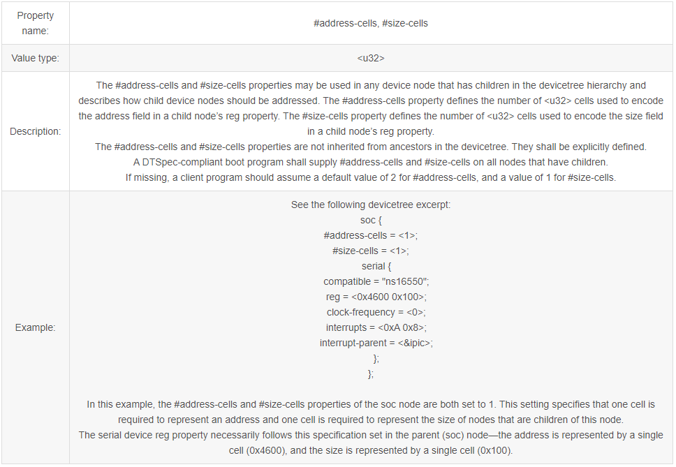
- 1、如果node"soc"中"#address-cells=<1>"、"#size-cells=<1>",那么子node"serial"中"reg"属性的解析为“addr1 = 0x0, size1 = 0x100, addr2 = 0x0, size2 = 0x200”:
soc {
    #address-cells = <1>;
    #size-cells = <1>;
    serial {
        reg = <0x0 0x100 0x0 0x200>;
    }
}- 2、如果node"soc"中"#address-cells=<2>"、"#size-cells=<2>",那么子node"serial"中"reg"属性的解析为“addr1 = 0x100, size1 = 0x200”:
soc {
    #address-cells = <2>;
    #size-cells = <2>;
    serial {
        reg = <0x0 0x100 0x0 0x200>;
    }
}- 3、如果node"soc"中"#address-cells=<2>"、"#size-cells=<0>",那么子node"serial"中"reg"属性的解析为“addr1 = 0x100, addr2 = 0x200”:
soc {
    #address-cells = <2>;
    #size-cells = <0>;
    serial {
        reg = <0x0 0x100 0x0 0x200>;
    }
}
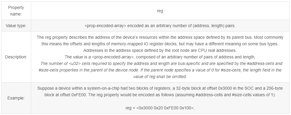
reg
“reg"属性解析出"address,length"数字,解析格式依据父节点的”#address-cells、#size-cells"定义。
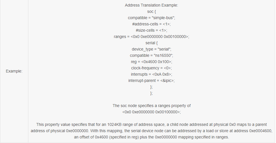
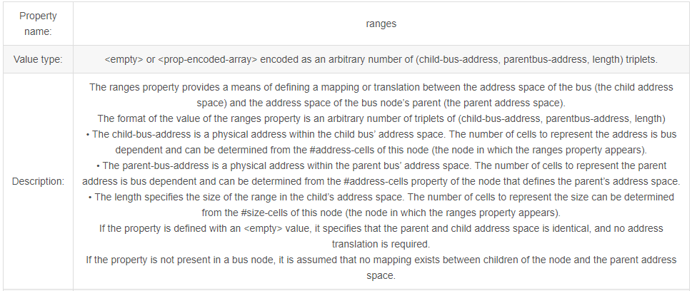
ranges
"ranges"属性用来做当前node和父node之间的地址映射,格式为(child-bus-address, parentbus-address, length)。其中child-bus-address的解析长度受当前node的#address-cells属性控制,parentbus-address的解析长度受父node的#address-cells属性控制length的解析长度受当前node的#size-cells属性控制。
interrupt property
和中断相关的node可以分成3种:
- “Interrupt Generating Devices”,中断发生设备,这种设备可以发生中断。
- “Interrupt Controllers”,中断控制器,处理中断。
- “Interrupt Nexus”,中断联结,路由中断给中断控制器。
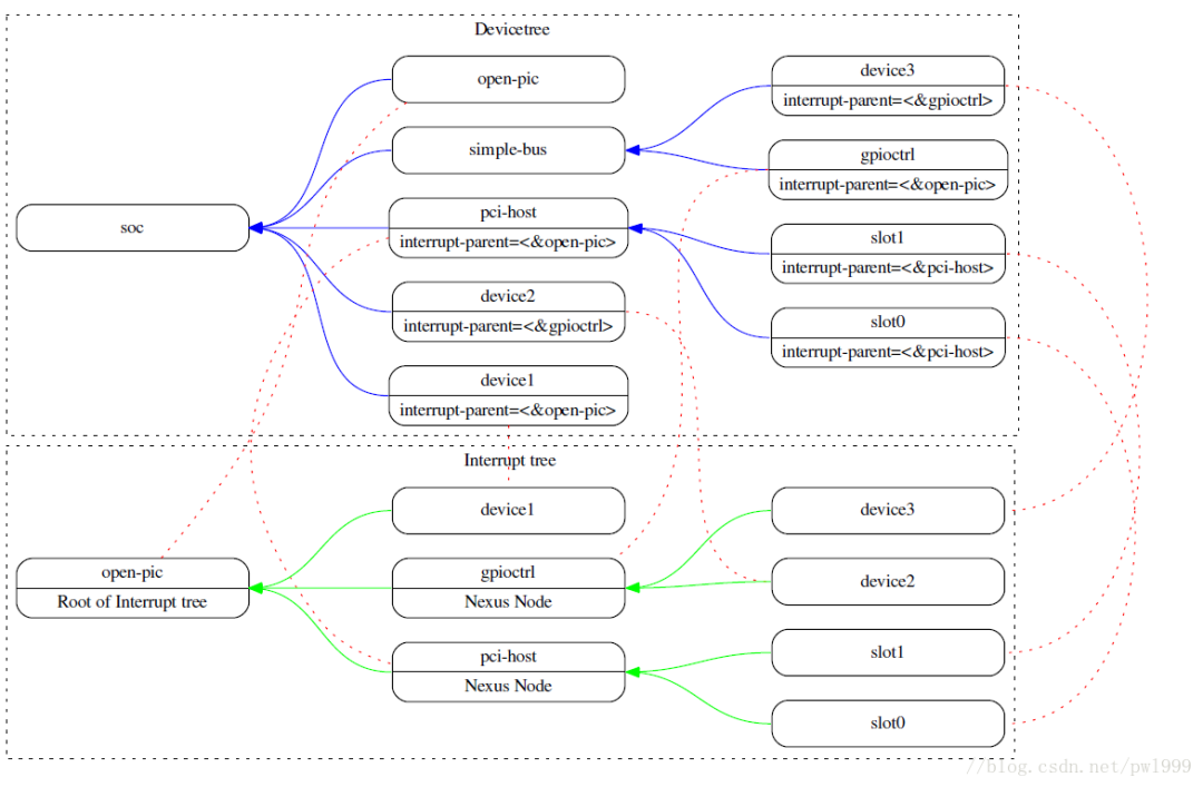
- "interrupts"属性用来定义设备的中断解析,根据其"interrupt-parent"node中定义的“#interrupt-cells”来解析。比如#interrupt-cells=2,那根据2个cells为单位来解析"interrupts"属性。
- "interrupt-parent"属性用来制定当前设备的Interrupt Controllers/Interrupt Nexus,phandle指向对应的node。
Property name: interrupt-parent Value type:Description: Because the hierarchy of the nodes in the interrupt tree might not match the devicetree, the interrupt-parent property is available to make the definition of an interrupt parent explicit. The value is the phandle to the interrupt parent. If this property is missing from a device, its interrupt parent is assumed to be its devicetree parent.
2 . Interrupt Controllers Property
- "#interrupt-cells"属性用来规定连接到该中断控制器上的设备的"interrupts"属性的解析长度。
- "interrupt-controller"属性用来声明当前node为中断控制器。
3 . Interrupt Nexus Property
- "#interrupt-cells"属性用来规定连接到该中断控制器上的设备的"interrupts"属性的解析长度。
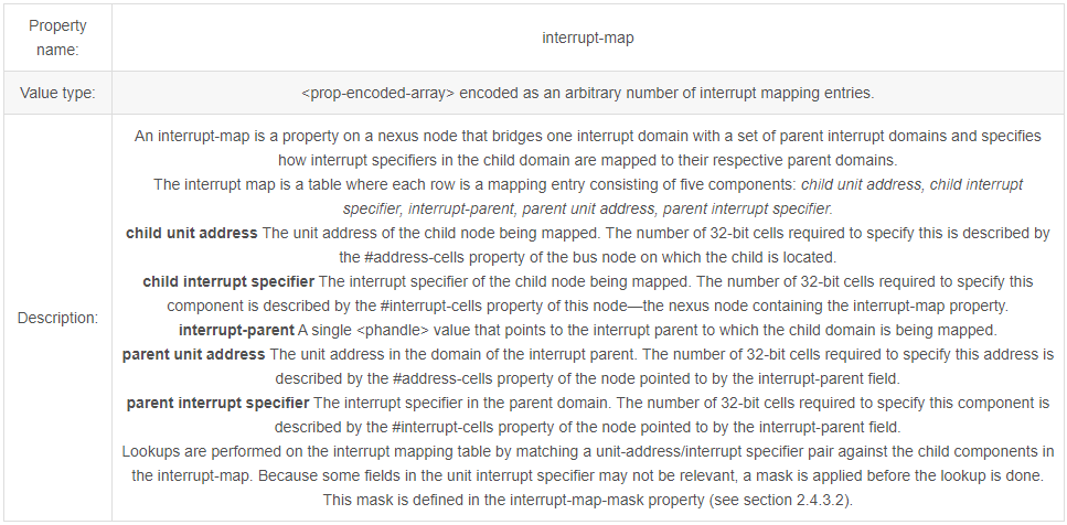
- "interrupt-map"属性用来描述interrupt nexus设备对中断的路由。解析格式为5元素序列“child unit address, child interrupt specifier, interrupt-parent, parent unit address, parent interrupt specifier”。
其中:
“child unit address”的cells长度由子节点的“#address-cells”指定;
“child interrupt specifier”的cells长度由子节点的“#interrupt-cells”指定;
“interrupt-parent”phandle指向interrupt controller的引用;
“parent unit address”的cells长度由父节点的“#address-cells”指定;
“parent interrupt specifier”的cells长度由父节点的“#interrupt-cells”指定;
soc {
    compatible = "simple-bus";
    #address-cells = <1>;
    #size-cells = <1>;
    open-pic {
        clock-frequency = <0>;
        interrupt-controller;
        #address-cells = <0>;
        #interrupt-cells = <2>;
    };
    pci {
        #interrupt-cells = <1>;
        #size-cells = <2>;
        #address-cells = <3>;
        interrupt-map-mask = <0xf800 0 0 7>;
        interrupt-map = <
        /* IDSEL 0x11 - PCI slot 1 */
        0x8800 0 0 1 &open-pic 2 1 /* INTA */
        0x8800 0 0 2 &open-pic 3 1 /* INTB */
        0x8800 0 0 3 &open-pic 4 1 /* INTC */
        0x8800 0 0 4 &open-pic 1 1 /* INTD */
        /* IDSEL 0x12 - PCI slot 2 */
        0x9000 0 0 1 &open-pic 3 1 /* INTA */
        0x9000 0 0 2 &open-pic 4 1 /* INTB */
        0x9000 0 0 3 &open-pic 1 1 /* INTC */
        0x9000 0 0 4 &open-pic 2 1 /* INTD */
        >;
    };
};
• For example, the first row of the interrupt-map table specifies the mapping for INTA of slot 1. The components of that row are shown here
child unit address: 0x8800 0 0
child interrupt specifier: 1
interrupt parent: &open-pic
parent unit address: (empty because #address-cells = <0> in the open-pic node)
parent interrupt specifier: 2 1